Outputs
These checks allow you to test the components in the WAZER that receive a signal from the controller to be activated during various operations. They will be frequently used in troubleshooting to identify the root cause of whatever issue the user is facing. These checks are also helpful for diagnosing hardware issues.
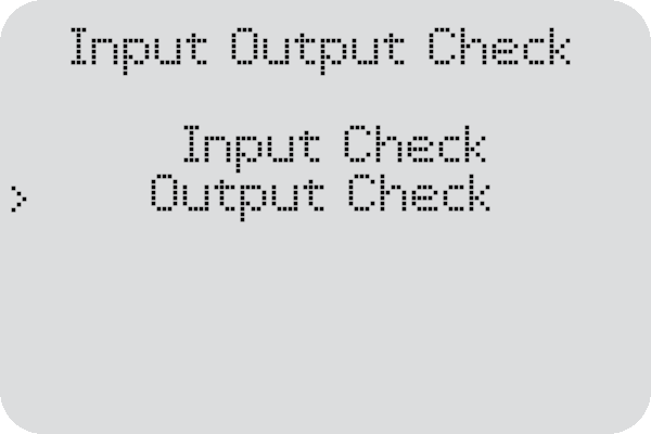
To navigate to the Output Checks menu, please follow this path on the User Interface Screen.
“Setup & Maintenance” > “Input/Output Check” > “Output Check”


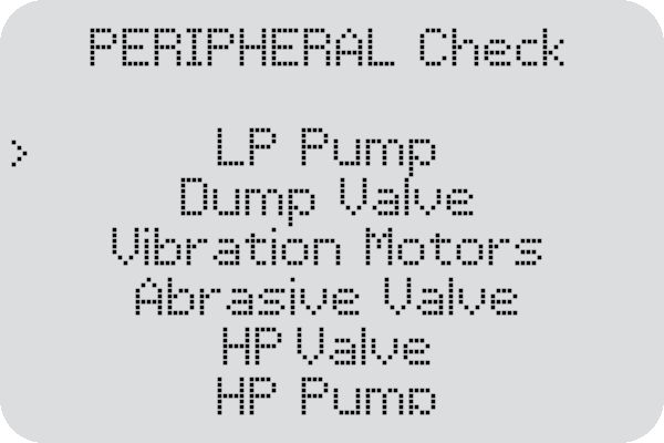
LP Pump
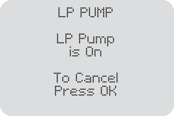
The LP Pump output check will turn on the low pressure pumps located in the rear of the machine. These pumps are responsible for draining the water level when needed and for running the used abrasive collection system.

During the test, the pumps will be turned on to activate the used abrasive collection system. You will hear the pumps turn on and see abrasive-filled water being pumped into the collection buckets.
If either side appears to have a weak stream please prime the plumbing to remove any air from the system. https://www.wazer.com/resources/maintenance/procedures/priming-the-plumbing
If you cannot see water exiting out of all 4 holes, please contact Support.
Dump Valve
The Dump Valve output check will open the valve that allows water to be drained out of the WAZER. The dump valve is controlled by a pinch valve that will not allow water to drain from the tank when it is closed and will allow water through when it is actuated.

During this test, a signal will be sent to the pinch valve to open for 6 seconds. Water will exit through the drain hose during this test so please make sure to be aware of where your drain hose will dump it.


Sometimes the drain hose can become kinked so please make sure to route it so that it does not pinch and prevent the water from flowing.

If the pinch valve does not open when this test is run, please contact Support.
Vibration Motors
The Vibration Motors output check will supply power to the vibration motors attached to the abrasive hopper. These motors are responsible for making sure the abrasive moves toward the center of the hopper to maintain an ideal abrasive flow rate.

During this test, you will hear the vibration motors turn on and begin vibrating the abrasive drawer and hopper. Please visually inspect the motors during this output check to make sure they are both spinning.


If you notice one or both of the motors is not spinning, or if one is spinning faster than the other please contact Support.
Abrasive Valve
The Abrasive Valve output check will open the abrasive pinch valve and allow abrasive to flow through the drop tube. This valves function is critical to allow abrasive to travel to the water stream to perform the cut.

During this test, the Abrasive Valve will open up to allow the abrasive to flow through. It will remain open for 7 seconds and then shut to stop the abrasive from flowing out of the hopper. Abrasive will exit through the drop tube during this test, we recommend placing a cup under the pinch valve so that this abrasive can be added back into the hopper.


If you are unable to see abrasive flowing out of the hopper while the valve is open, please follow the instructions here to clear any clogs in the hopper. If you are still unable to see abrasive flowing after clearing any clogs, please reach out to Support.
HP Valve
The HP Valve output check will open the High Pressure valve and let water travel through the high pressure system and exit the nozzle. The HP Valve contains a solenoid that will open the valve to allow water to travel to the nozzle and close to stop the water stream.

During this test, you will hear the HP Valve ‘click’ open and remain open for 7 seconds, then hear another ‘click’ when the valve closes. You will also see low-pressure water exit through the nozzle or abrasive inlet. The pump will not turn on during this output check.


If you cannot hear the ‘click’ when you run this output check, please see the ‘Continued Troubleshooting’ steps on this page.
HP Pump
The HP Pump output check will turn on the pump in a low power mode to ensure that it is able to turn on when the signal is sent. The HP Pump is located inside of the pump box and is powered by a large AC motor that turns the pump to create the pressure needed for cutting.
During this test you will hear the HP Pump power on and run for several seconds before turning off. The HP Valve will not be opened during this test, so you will not see water exiting the nozzle. This check is important for making sure the Pump Box Signal Cable is properly connected and the pump can receive the signal from the controller to turn on. This output check will often be used when troubleshooting any issues with the pump.


If your pump does not turn on during this test, make sure the LED on both GFCI cables are lit up and that the Pump Box Signal Cable is properly seated into the connector. If your pump still does not turn on, contact Support for help.