Advanced Cut Files
More Advanced Cuts for more experienced WAZER Users or Curious beginners
In this Article you will find:
A gallery showcasing the advanced cut files we have available
Instructions on how to assemble these files
Some of the pictures with important fine details can be enlarged by clicking on them.
WAZER has been hard at work compiling more advanced cut files requiring assembly and post-processing techniques. Browse through our library and download whatever catches your eye! Assembly instructions for each file can be found below the gallery.
__________________________________________________________________________________________
Tools needed for these assemblies:
Pliers
Hammer
Deburring Tool
File
Tool Holder Assembly Instructions
Step 0: Download the Design file from our Downloads page and cut the parts on materials of your choice
This is what the cut will look like immediately after cutting has finished.
Step 1: Deburring
Use a deburring tool to clean up all burrs on the pieces.
Step 2: Filing
Use a file to clean up the sharp tab remnants.
Step 3: Lining up the Dovetail Joint
Make sure that the draft angles of the pieces are lined up by flipping the hook piece over before locking the joint with a hammer.
Line up the dovetails once you ensure that the draft angles correspond with each other.
Step 4: Locking the Dovetail Joint
Hammer the joint together with a hammer until the pieces are flush with each other.
Step 5: Bending the Back Piece
Using a clamp or pliers, bend the back piece along the relief cuts to 90 degrees.
The bent piece should look like this.
Step 6: Inserting the Partitions
Insert partitions into base piece holes using a mallet or hammer.
Step 7: Attaching the Box Joints
Attach back piece to base piece by lining up pieces and hammering the box joints together.
Hammer joints as far into each other as they will go. This will ensure a tight and strong joint.
Step 8: Bending the Hook
Bend hook into shape using a vice or pliers. Each bend is 90 degrees. These angles can be slightly adjusted for tightness once it is test fit over the machine.
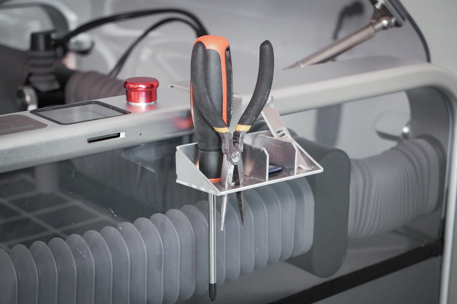
Finished Product
The finished product can be used to hold a multitude of tools and other important items, an SD card, screws, and the Multitool Welcome Cut.
The hook goes around the aluminum hoop on either side of the machine. The fit is intentionally tight so that the tool holder does not move when being used. Hook the far end of the hook over the inside of the machine, and then press the top of the hook down until it fully seats on top of the hoop.
Bridge Assembly Instructions
Step 0: Download the Design file from our Downloads page and cut the parts on materials of your choice (must be 2.3 mm thick or joints might not fit)
This is what the cut will look like immediately after cutting has finished.
Step 1: Deburring
Use a deburring tool to clean up all burrs on the pieces.
Step 2: Filing
Use a file to clean up the sharp tab remnants.
Step 3: Twist Joints
Push the two skinny stair pieces through their cut outs in the bridge side pieces vertically, as shown.
Twist the joint once or twice with pliers or by hand to ensure that the piece will lock
Step 4: Insert Main Span
Insert the main span’s tabs into two holes on the bridge sides, as shown.
The fit of these tabs into their holes is intentionally loose.
Step 5: Adding the other side of the Bridge
Line up the two stairs and two tabs of the main span with their respective holes on the other side of the bridge and push them through, as shown.
This operation might take a bit of force and wiggling.
Step 6: Locking the Twist Joints
Twist the top of the stair piece away from the middle of the bridge with pliers until they are parallel to the main span piece, as shown. Repeat for the other stair.
Once fully twisted into place, the bridge should feel solid and the pieces should not wiggle.
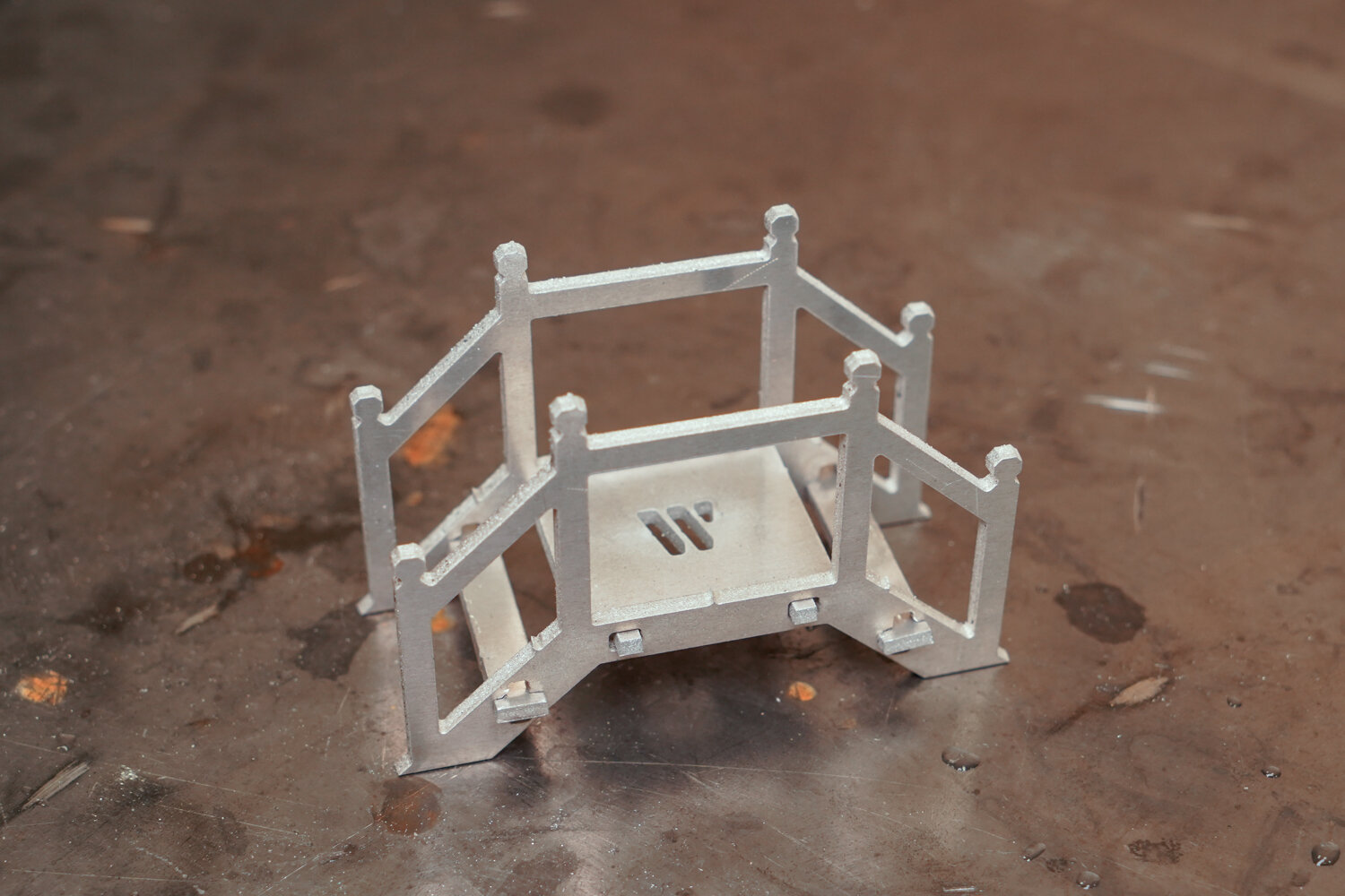
The Final Product
Using water jetting, an endless array of complex creations awaits. This bridge serves as a demonstration of one type of joint that can be used to take a 2 Dimensional cutting operation and turn it into a 3 Dimensional end result.
Mechanical Iris Assembly Instructions
This assembly requires additional tools and hardware to complete.
Additional Tools needed:
Sandpaper or power sander
4mm and 2.5mm hex wrench
8mm and 6mm sockets or wrenches
Lubricant
Hardware needed:
1.5mm thick Aluminum, at least 150 x 265 mm
10 M5 Bolts
10 M5 Locking Nuts
10 M3 Bolts
10 M3 Locking Nuts
Step 0: Download the Design file from our Downloads page and cut the parts on materials of your choice
This is what the cut will look like immediately after cutting has finished.
This is a complex assembly with many parts, they are labeled above to aid in the assembly process
Step 1: Deburr All parts
Since there are a multitude of sliding surfaces in this assembly, all parts need to be thoroughly cleaned and deburred so that the assembly moves smoothly. This includes deburring of the holes.
Step 2: Sand/Polish the pieces
After deburring, a light sanding and washing is also recommended to completely ensure smooth sliding.
The more time spent on post-processing, the more smoothly the Iris will operate. Polishing and oiling is unnecessary but will allow the mechanism to operate more smoothly.
[WARNING] Wear gloves when sanding as burrs are very sharp and can cut you.
Step 3: File off Tabs
There are many tabs used when cutting this assembly to keep the pieces in place during cutting. Use a file to remove the tab remnants.
Tab removal is not necessary to the operation of this assembly, but removal provides a better looking end result.
Step 4: Assemble the Backing Plate and Carrier
Use 5 M5 bolts and nylon locking nuts to assemble the backing plate and carrier together.
Put the bolts in the pictured slots in the carrier and align them with the holes in the backing plate. Ensure the handles are opposing each other.
Tighten the nuts with a 4mm hex screwdriver and 8mm wrench enough so that the plates can still slide but will not jiggle up and down.
Step 5: Lube the Carrier and Backing Plate
At this point your assembly should look like this once all 5 bolts have been installed. The carrier and backing plate have a large contact area and lubricant will make the sliding between them easier.
Spray or drip lubricant between the two plates. Slide the pieces to distribute the lube.
If you are having difficulty sliding the two pieces, loosen the bolts. If problems still persist, more post processing (polishing, de-burring, etc.) might be necessary
Step 6: Attach Iris Blades
Attach the blades to the assembly using an M5 Bolt and locking nut
Align the larger hole in the blade with the hole towards the middle in the backing plate.
Tighten the nuts using a 4mm hex screwdriver and 8mm wrench enough so that the blades can still slide but will not jiggle up and down. Repeat for all 5 blades.
Step 7: Attach Arm to Blade
Attach the arms to the blade using an M3 Bolt and locking nut.
Align a hole in the arm with the smaller hole in the blade and the slot in the backing plate.
Insert the M3 bolt and loosely attach the nut to the back of the assembly.
Step 8: Attach Arm to Carrier
Align the other hole in the arm with the pictured hole in the carrier and the aligned slot in the backing plate.
Use a 2.5mm hex screwdriver and 6mm wrench to tighten the nut and bolt. Pliers also work well in place of the wrench. Tighten all the nuts enough so that the arms can still slide but will not jiggle up and down. Repeat steps 7 and 8 for all 5 arms.
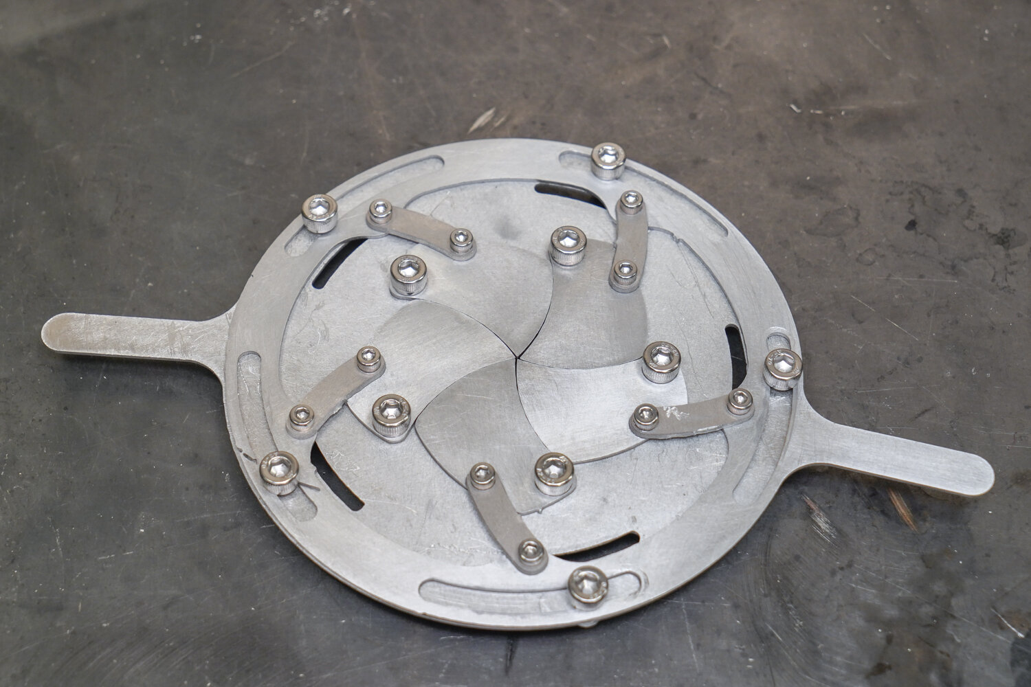
The Final Product
Congratulations on completing your Mechanical Iris! Water jet cutting grants you the precision and accuracy needed to make exceedingly complicated mechanisms with multiple moving parts, like this one. The more the assembly is cycled, the easier it will get to move.